
Current Transformers Overview and Selecting the right CT based on Your Industry Application
The focus of this study is to understand the role played by a critical component in the power supply ecosystem – Current Transformers (CT). How does a CT work, what are the different types of CT, its various applications and other important aspects are discussed in detail.
- Introduction to Transformers
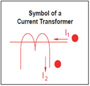
- What is a Current Transformer?
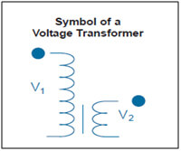
- What is a Potential (or Voltage) Transformer?
- How Current Transformers work?
- Important Characteristics of Current Transformers
- How to select the right Current Transformer?
- Applications of a Current Transformer
- Current transformer types
- Standards and compliance
- Current Transformers from KSI
Introduction to Transformers
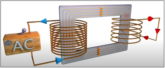
A transformer is basically a passive electrical device that works on the principle of Faraday’s law of Electro-Magnetic Induction by converting electrical energy from one value to another. Transformers are capable of either increasing or decreasing the voltage and current levels of power supply without modifying supply frequency or the amount of electrical power being transferred.
A transformer basically consists of 2 wound electrical coils of wire – primary and secondary. The primary is connected to the source of power and the secondary is connected to the power delivery end. These two coils are not in electrical contact with each other but are instead wrapped together around a common closed magnetic iron circuit called the core. This soft iron core is not solid but made up of individual laminations connected together to help reduce the core’s losses. When AC current passes through the primary coil, a magnetic field is induced into the core which transmits a proportional voltage (or current) into the secondary coil.
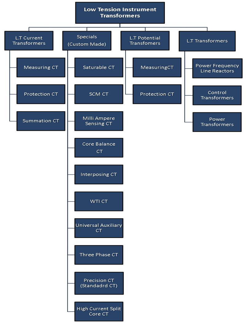
Transformers can be broadly categorised as Power Transformers and Instrument Transformers based on their application. While power transformers are used in power transmission, instrument transformers find primary application in measurement of current and voltage.
Instrument Transformers are used in AC power systems for measurement of electrical quantities i.e. voltage, current, power, energy, power factor, frequency. Instrument transformers are also used with protective relays for protection of the power system. Instrument Transformers are of two types – Current Transformers and Potential (or Voltage) Transformers.
What is a Current Transformer?
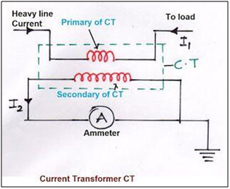
Current Transformer (C.T.) is a type of Instrument Transformer that converts primary currents to proportional secondary currents which are appropriate to the connected measuring instruments. Technically they can reduce or multiply Alternating Current (AC). However, in practical usage, the reduction function is widely applied for usage in measuring instruments such as Ammeters. Current Transformers are series connected electromagnetic devices consisting of an Iron core, electrical grade laminations and copper wound coils.
What is a Potential (or Voltage) Transformer?
Potential or Voltage Transformer (P.T.) is a type of Instrument Transformer that measures high voltage on primary by stepping down to a measurable voltage value. Technically they can reduce or multiply the primary voltage onto the secondary side. However, the practical application of a voltage transformer is to step down the voltage to a safe limit value so that it can be easily measured by an ordinary low voltage instrument like a voltmeter, wattmeter or watt-hour meter. They are a parallel connected type of instrument transformers.
How Current Transformers work?
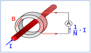
The basic principle of a Current Transformer is the same as described above. Whenever an Alternating Current flows through the primary winding, alternating magnetic flux is produced, which then induces a proportional Alternating Current in the secondary winding.
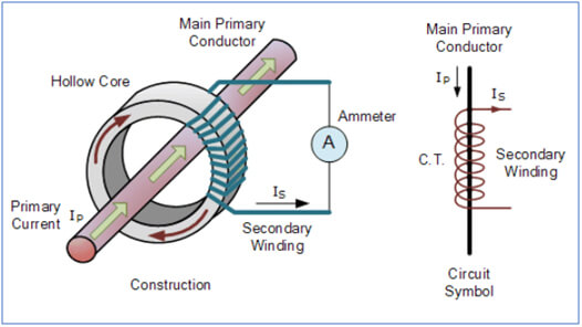
However, there is an important operational difference in Current Transformers when compared to other types. CT generally consists of only one or very few turns as its primary winding. It could just be a bar or a conductor placed through a hole (as in the picture above). Or it could be a heavy duty wire around the core. In contrast, the secondary would have a large number of turns wound on a laminated core of low-loss magnetic material.
The primary current is controlled by an independent external load and the secondary current has ratings of 1A or 5A which are conducive to measuring instruments. It is important that the insertion of the CT for current measurement purpose does not affect the primary circuit operations.
Current Transformers are basically step down transformers which take low tension (indicating low voltage) and consequently high current as input. Thus, they are also referred to as Low tension Current Transformers (LTCT).
Important Characteristics of Current Transformers
Current Ratio – Also known as the Turns Ratio (in general terms) is the ratio of the primary current to the secondary current. This value is obviously equal to the ratio of number of turns in the primary and secondary coils. The current ratio of a CT is usually high. The secondary current ratings are typically 5A, 1A and 0.1A. The corresponding current primary ratings vary from 10A to 3000A or more.
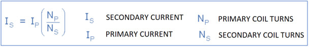
For instance, an Ip / 5A ratio Current Transformer will deliver a secondary current (Is) of 0-5A which is proportional to the current measured at the primary (Ip). In the case of 100/5 CT, the primary current is 20 times greater than the secondary current so when 100 amps are flowing in the primary conductor, it will result in 5 amps flowing in the secondary winding.
However, it is important to note that 100/5 rating and 20/1 rating of Current Transformers are not the same, even though their current ratios are equal. These rating numbers actually represent the absolute values of “input/output current rating”.
Polarity – The polarity of a CT is determined by the direction of coil winding around the core of the CT (clockwise or counter-clockwise) and by the way the leads, if any, are brought out of the transformer case. All current transformers have subtractive polarity. Maintaining proper polarity is important when installing and connecting current transformers to power metering and protective relays.
Accuracy Class – Accuracy Class describes the performance characteristics of a Current Transformer and the maximum burden that can be allowed on its secondary circuit. Depending on their Accuracy Class, Current Transformers are classified for Metering Accuracy or Relaying Accuracy (Protection CTs). A CT can have ratings for both groups.
Metering accuracy CT can deliver high accuracy current measurement over short ranges of current. Whereas Relaying Accuracy CT is meant for larger ranges of current even if the accuracy is of a lesser degree.
CT Accuracy Class is displayed on its label or nameplate. It consists of three parts: rated ratio accuracy rating, class rating, and maximum burden.
How to select the right Current Transformer?
The following parameters that must be evaluated before selection of the appropriate Current Transformer for an application are:
- Voltage of the circuit
- Rated primary current
- Rated load on Secondary side
- Rated Secondary current
- Accuracy Class Rating
The choice must also consider the conductor profile and the maximum intensity of the primary circuit.
Applications of a Current Transformer
The two main application areas of Current Transformers are current measurement and protection. They are also used for isolation between high voltage power circuits and measuring instruments. This not only ensures safety of the operator but also of the end device in use. It is recommended to apply current transformers for currents of 40A or higher.
CT in Measurement – A metering Current Transformer is designed to measure current on a continuous basis. They work with a high degree of accuracy but within the rated current range. Current transformers have a primary winding to which the current to be measured is fed. Measuring instruments are connected to a secondary winding. This allows them to be used in combination with measurement equipment and power monitoring products – from simple energy meters to power quality meters such as:
- Ammeters
- Kilowatt-hour meters
- Measurement units
- Control relays
Current error and phase displacement limits are determined by the accuracy class. Accuracy classes are: 0.1, 0.2, 0.5 and 1. If input current exceeds the rating, the metering CT will saturate thereby limiting the current level within the measuring instrument. Core materials for this type of CT typically have low saturation levels, such as nano-crystalline.
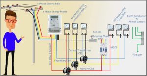
Current Transformers in Power Protection System– A Protection Current Transformer is used to reduce the currents in power systems thereby protecting it from faults. These Current Transformers measure the actual current in the primary side and produce proportionate currents in their secondary windings which are completely isolated from the primary circuit. This replica current is then used as an input to a protective relay, which will automatically isolate part of the power circuit in case of a fault. Since only the faulty portion is isolated, the rest of the installation can continue to function normally.
Some of the important application scenarios where CTs are installed are:
- For control in high-voltage electrical sub-stations and the electrical grid
- To activate the protective relay in case of a fault current and isolate a part of or the full system from the main supply
- Commercial metering
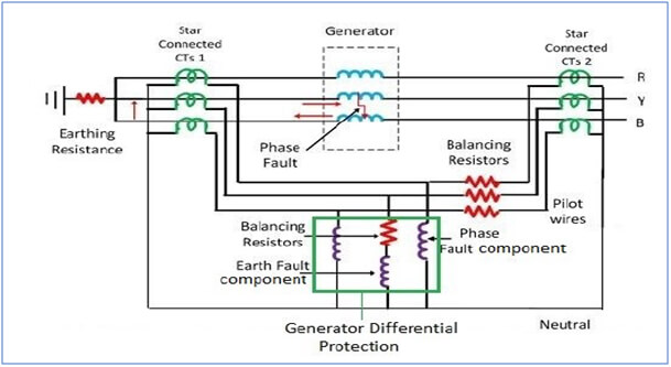
- Earth fault Protection/Differential Protection/Bus–bar protection system
- Motor – Generator sets
- Control Panel (VCB, AMF, APFC, MCC, PCC and Relay panels) and Drives
- Standard CT for Laboratory purpose
- Bushing type, oil-immersed CT in Power transformer
- Current sensing, recording, monitoring and control
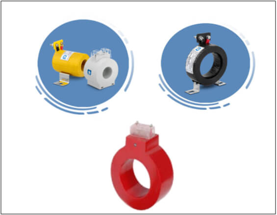
Current transformer types
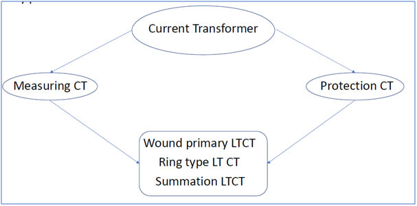
Wound primary – In this type, the primary winding is physically connected in series with the conductor that measures the current. The primary winding has a single turn and is composed inside the transformer. Wire wound Current Transformer can be used to measure currents in the range of 1A to 100A.
Bus Bar – In this type, the bus bar of the main circuit itself acts as the primary winding with a single turn. So the bar type transformer has only secondary windings. The body of the CT itself provides insulation between the primary circuit and ground. By using oil insulation and porcelain bushings, such transformers can be applied at the highest transmission voltages.
Ring Type – In this type, the CT is installed over a bus bar or an insulated cable and only a low level of insulation is present on the secondary coil. To obtain non-standard ratios or for other special purposes, more than one turn of the primary cable may be passed through the ring. The core is usually laminated silicon steel and the windings are of copper.
Summation – Summation transformers are used for comparing the relaying quantities derived from the current in the three phases of the primary circuit. This is done by converting the three-phase quantities into the single phase quantity. The line Current Transformers are connected to the primary of the Auxiliary Current Transformer. These transformers are used for ensuring proper functioning of relay circuits.
Standards and compliance
- IS 61227, 2016
- IEC 61869, C-57
- IS 2705 (Part 1):1992 for General Requirements
- IS 2705 (Part 2):1992 for Measuring Current Transformers
- IS 2705 (Part 3):1992 for Protective Current Transformers
- IS 2705 (Part 4):1992 for Protective Current Transformers for Special Purpose Application
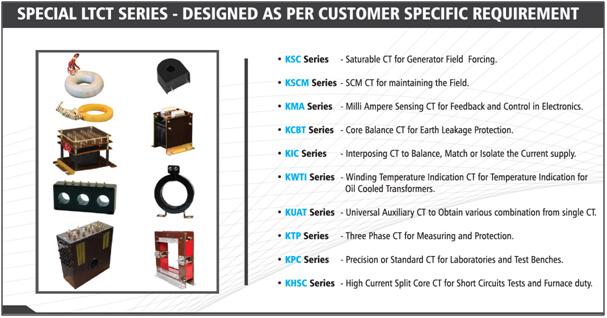
Current Transformers from KSI
KS Instruments is a leading player in the design and manufacturing of high accuracy LT Current transformers for measuring and protection applications. KSI CT products come in tape wound, resin cast and ABS enclosure constructions. KSI has a wide range of catalogue products to suit all needs. These products have been validated by our clients for high efficiency, robust performance and long service life.
Measuring CT can lower the high current in control panels & panel boards at a pre-determined ratio such as 100:1. Offered as Ring type, also called as window type, allow bus bars or cables to be passed through the CT and act as a Primary for the CT. The safe, low VA burden and click fit CT makes it very convenient to use in retrofit applications without disconnecting any cable. This saves down-time period and revenue loss which would occur due to shut down of the plant during installation of the Current Transformer.
Protection Current Transformers are used to activate the protective relay in case of a fault current and isolate a part of or the full system from the main supply.
KS Instruments has an expert design engineering team that can design and manufacture custom components for specific Current Transformer applications.
Features
- Designed as per IS-16227, C-57 or Customer Requirement
- Secondary Current 5A or 1A
- Primary Current up to 5000A
- Secondary Burden 1VA to 30VA
- Dual Ratios can be offered
- High Accuracy on request
- Mounting arrangement offered on request
- Construction style – Varnished Fiberglass tape, PVC Tape Insulated, Resin cast, ABS or Glass filled Nylon Moulded
Certifications & Approvals
- KSI is approved and widely used for metering applications at various State Government power supply companies such as BESCOM, HESCOM, CHESCOM, MESCOM.
- KSI Current Transformers are tested and certified at CPRI Bengaluru, India (NABL)
| Description of test | Tested At | Standard |
| 1.Routine Test
2.Short Time Current Test 3.Dynamic Current test 4.Tempature Rise Test |
Central Power Research Institute Bengaluru |
IS-16227 Part-1,2
IEC 61869 IS-2705 |
KSI Product Range
| WOUND PRIMARY MEASURING CURRENT TRANSFORMERS | |||
| Primary Current | Secondary Current | Accuracy Class | Output (Burden) |
| 1A to 200A | 1A, 5A Or as per customer requirement | CL-5, CL-3, CL-1, CL-0.5, CL-0.2, CL-0.1, CL-0.5S, CL-0.2S | 1 VA to 30 VA |
| WOUND PRIMARY PROTECTIVE CURRENT TRANSFORMERS | ||||
| Primary Current | Secondary Current | Accuracy Class | Accuracy Limit factor (ALF) | Output (Burden) |
| 1A to 200A | 1A, 5A Or as per customer requirement | Standard – 5P, 10P, 15P
Special – PS and XPS |
5, 10, 15, 20 & 30 | 1 VA to 30 VA |
| RING TYPE MEASURING CURRENT TRANSFORMERS | ||||
| Primary Current | Secondary Current | Accuracy Class | Output (Burden) | Min ID |
| 50A to 5000A | 1A, 5A Or as per customer requirement | CL-5, CL-3, CL-1, CL-0.5, CL-0.2, CL-0.1, CL-0.5S, CL-0.2S | 1 VA to 30 VA | 30mm
|
| RING TYPE PROTECTIVE CURRENT TRANSFORMERS | |||||
| Primary Current | Secondary Current | Accuracy Class | Accuracy Limit factor (ALF) | Output (Burden) | Min ID |
| 50A to 5000A | 1A, 5A Or as per customer requirement | Standard – 5P, 10P, 15P,
Special – PS and XPS |
5, 10, 15, 20 & 30 | 1 VA to 30 VA | 30mm |
| SUMMATION CURRENT TRANSFORMERS | |||
| Primary Current | Secondary Current | Accuracy Class | Output (Burden) |
| 1A, 5A
Or as per customer requirement |
1A, 5A Or as per customer requirement | For measuring series: CL-1, CL-0.5, CL-0.2
For protective series: 5P, 10P, 15P |
1 VA to 30 VA |
Despite a wide range of KSI Catalogue products, in several cases your application may demand a custom solution. With the backing of a strong design team and an in-house testing facility, KSI can offer Custom Low Tension Current Transformers solutions to your design challenges with ease.
Feel free to let us know your custom requirements for us to offer our solution!


Author: Anuradha C
An integral part of the content creation team at KS Instruments, Anuradha is a corporate trainer in the IT/telecom domain with over 18 years of experience. She served in senior technical and management positions in Huawei and TCS for 10+ years
Recent Posts
- Why are isolation transformers used in UPS for data centers?
- Why Current Transformers are used in Electrical Panels?
- The critical role of Current Transformers in Ammeter measuring applications
- Isolation Transformers for Medical Industry Applications – KSINSTRUMENTS
- Summation Measuring Current Transformers for Power Systems
CLIENTS