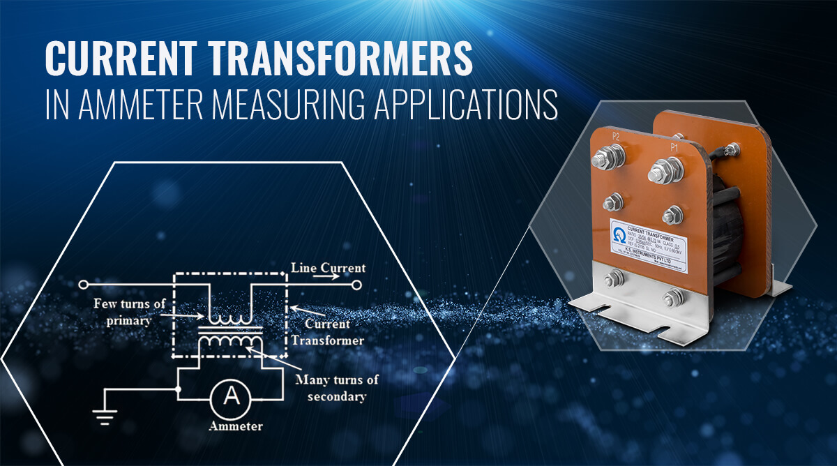
The critical role of Current Transformers in Ammeter measuring applications
What is the function of ammeter?
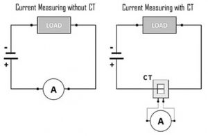
The principal function of an ammeter is to continuously measure the magnitude of current flowing through a closed circuit. When the magnitude of current measured is not high, ammeters installed in series with the circuit are adequate. However for larger magnitude currents, they are usually accompanied by a measuring type Current Transformer. The CT ensures that the current is stepped down and then fed into the ammeter.
Accuracy of reading and reliability over long durations of time are the two critical requirements of measuring instruments such as ammeters. Current transformers help to perform these critical functions. Modern day AC ammeters even come with built-in current transformers.
Why to use a Measuring Current Transformer with an Ammeter?
An ammeter works by measuring the voltage drop on a shunt resistor. The ammeter is connected in series with the circuit it measures, so that the current flow is the same.
The main characteristic of the ammeter is that it must have very low resistance and inductive reactance. When the primary side of the CT is energized, the measurement equipment nearly acts as a short circuit which keeps the secondary voltage very low. This voltage will increase significantly if the short circuit is removed.
Measuring type Current Transformers are used in conjunction with ammeters for the following purposes:
- To measure high currents that are stepped down to a standard output ratio
- To standardise the output current range to either 5 A or 1 A.
- To isolate the measuring instrument from the main power circuit.
It is not easy to design measuring instruments such as ammeters or voltmeters for high current / voltage values commonly used in power systems. Issues of excess heat generation and wear & tear arise.
Furthermore, handling a wide range of currents would not be practically suited to manufacture measuring instruments on a mass production scale.
Therefore, a measuring Current Transformer provides a convenient way of safely monitoring the actual electrical current flowing in an AC transmission line using a standard ammeter. They transform current at an accurate ratio and allow the attached ammeter to gauge the current without actually running full power through it.
Let us understand the role of a 100/5A ratio CT in the ammeter measurement circuit. For example, if the current in the circuit is in the 100A range, then the CT will step down the current to 5A range and then feed it into the ammeter. So an actual value of say 60A in the main circuit will get translated into 3A in the ammeter. The ammeter would then reconvert the value to the original range and display the measured output.
It is important to match the VA rating of the CT with the VA rating of the ammeter.
Characteristic features of measuring CTs for ammeters
Current Transformer(CT) Ratio – The most common ratio options for CT usage with ammeters are step down to 5A or 1A. If input current exceeds the rating, the metering CT will saturate thereby limiting the current level within the measuring instrument.
What is the ratio- The ratio of … / 5A to a CT (Current Transformer) and Ammeters has the following meaning?
- … is the maximum value of current measurement capability in an Ammeters or CT.
- / 5A is the maximum current value received by Ammeters or the CT output is 5Ampre, when the maximum current value is measured.
Example:
In an electric panel, use an Ammeters with a value of 100 / 5A, and the installed CT also has a value of 100 / 5A.
Then when the electric current in the electrical panel circuit flows by 100 Ampere, CT will capture the induction of the electrical circuit by 100 Amperes in the Primary Coils, then the Secondary Coils stepdown the Electric current to 5A, and sends an electric current of 5 Ammeters, and then the Ammeters will convert the 5 Ampere electric current again to 100Ampere according to the actual measurement results
100 / 5A means “Every measured electric current is 100Amperes, then it is converted to 5Amperes”
Then, when the current is 80 Ampere, CT will change the value of 80 Amperes to:
4 amperes, with calculations, as follows:
80Ampere: (100/5)
80 Amperes: 20 = 4 Amperes.
If the actual current value is 80Ampere, then CT 100/5 will convert it to 4 Ampere, and then the electric current value is flowed to the Ammeters to be converted back to be shown to be the actual current value of 80 Ampere.
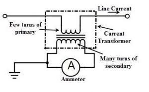
Coils – The primary coil of the CT has one or more turns of heavy wire. It is always connected in series in the circuit in which current is measured. The secondary coil is made up of many turns of fine wire connected across the ammeter terminals. The secondary must never be open-circuited, as the primary may not be connected to a source constantly. This will prevent the core from becoming completely magnetized, as a result of which the instrument may no longer read accurately. In measuring currents of 50A and above, it is convenient and technically sound for the primary winding of a CT to have one turn only.
Construction – Ring type, plastic case, resin cast are the most common options. With respect to conductor rating, the appropriate CT selection depends on the conductor profile and the maximum intensity of the primary circuit. There are limitations of dimension as well, the CT may have to fit on a busbar or in switchgear. Sometimes, the CT is supplied with a secondary winding only, the primary being the cable or busbar of the main conductor which is passed through the CT aperture, especially in ring CTs. Whether the installation is indoor or outdoor also influences the construction and material choice. Core materials for this type of CT typically have low saturation levels, such as nano-crystalline. They are generally available in wound or ring type.
Accuracy – Depends on several factors such as rating factor, temperature, load, external EMI, burden (VA), saturation class and the selected tap (for multi-ratio CTs). It is also important to ensure that the magnetising current is low enough so that the error limit for the accuracy class is not exceeded. This is achieved by selecting suitable core materials and the appropriate cross-sectional area of core.
Class designation is an approximate measure of the accuracy. For instance, Class 1 CTs have ratio error within 1% of rated current.
Accuracy Class may vary based on the intended application
- 0.1 – Precision Test & Measurement
- 0.2 – Precision Grade Meters
- 0.5 – Tariff kWh Metering
- 1.0 – Commercial kWh Metering
Accuracy classes for various types of measurement are specified in the relevant IEEE (ANSI), CAN/CSA, AS or BSEN /IEC 60044-1.
Measuring Current Transformers from KS INSTRUMENTS
KS Instruments is a leading player in the design and manufacturing of high accuracy Low Tension Current transformers for measuring and protection applications. KSI Current Transformers products come in tape wound, resin cast and ABS enclosure constructions.
KSI has a wide range of catalogue products to suit all needs. These products have been validated by our clients for high efficiency, robust performance and long service life. KS Instruments has an expert design engineering team that can design and manufacture custom components for specific Current Transformer applications.
Measuring Current transformers from KSI are widely employed to measure power circuit currents using measuring instruments such as Ammeters, Kilowatt-hour meters and power factor meters. They work with a high degree of accuracy within the rated current range. They comply with the specified accuracy class as in IEC 60044-1. The secondary current is substantially proportional to the primary within a working range of about 5–120% of its primary rated current.
KSI is approved and widely used for metering applications at various State Government power supply companies such as BESCOM, HESCOM, CHESCOM, and MESCOM. KSI Current Transformers are tested and certified at the reputed CPRI Bengaluru, India (NABL).
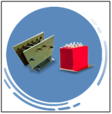
KWM Series (Wound Primary Measuring Current Transformers)
KWM Series are a range of Measuring Current Transformers. These CTs measure current flowing through the primary conductor by converting them to a measurable value.
Features:
- Designed as per IS-16227, IEC-61869, C-57 or Customer specific requirement
- Approved and widely used by various State Power Supply companies
- Requires little or no maintenance
- Tested and certified at CPRI Bangalore, India (NABL)
- Secondary Current 5A or 1A
- Primary Current up to 5000A
- Secondary Burden 1VA to 30VA
- Dual Ratios can be offered
- High accuracy on request
- Mounting arrangement on request
- Construction Styles Offered – Varnished Fiberglass or PVC Tape Insulated, Resin cast, ABS or Glass Filled Nylon Moulded
Learn More: KWM Series – Wound Primary Measuring Current Transformers
KRM SERIES (Ring Type Measuring Current Transformers)
KRM Series are a range of Measuring Current Transformers. This series of Ring type, also called window type, allows bus bars or cables to be passed through the CT and act as a Primary for the CT.
Features:
- Designed as per IS-16227, IEC-61869, C-57 or Customer specific requirement
- Approved and widely used by various State Power Supply companies
- Requires little or no maintenance
- Tested and certified at CPRI Bangalore, India (NABL)
- Secondary Current 5A or 1A
- Primary Current up to 5000A
- Secondary Burden 1VA to 30VA
- Dual Ratios can be offered
- High accuracy on request
- Mounting arrangement on request
- Construction Styles Offered – Varnished Fiberglass or PVC Tape Insulated, Resin cast, ABS or Glass Filled Nylon Moulded
Learn more: KRM SERIES – Ring Type Measuring Current Transformers
KSUM Series – Summation Measuring Current Transformers from KSI
KSU Series are a range of Summation current transformers. Summation CTs are used to sum secondary currents of several main CTs and supply to a single meter or relay.
Features:
- Designed as per IS-6949 or Customer specific requirement
- Approved and widely used by various State Power Supply companies
- Requires little or no maintenance
- Tested and certified at CPRI Bangalore, India (NABL)
- Secondary Current 5A or 1A
- Primary Current up to 5000A
- Secondary Burden 1VA to 30VA
- Dual Ratios can be offered
- High accuracy on request
- Mounting arrangement on request
- Construction Styles Offered :
- Varnished Fiberglass or PVC Tape Insulated
- Resin cast
- ABS or Glass Filled Nylon Moulded
Learn more: KSUM Series – Summation Measuring Current Transformers from KSI
Download KS INSTRUMENTS Product Catalog

Author: Anuradha C
An integral part of the content creation team at KS Instruments, Anuradha is a corporate trainer in the IT/telecom domain with over 18 years of experience. She served in senior technical and management positions in Huawei and TCS for 10+ years
Recent Posts
- Why are isolation transformers used in UPS for data centers?
- Why Current Transformers are used in Electrical Panels?
- The critical role of Current Transformers in Ammeter measuring applications
- Isolation Transformers for Medical Industry Applications – KSINSTRUMENTS
- Summation Measuring Current Transformers for Power Systems
CLIENTS